


Sensors
The Best Sensors Manufacturer!
Jinan Nake Test Equipment Co., Ltd. is a high-tech entity enterprise integrating R&D, production and sales established in July 2009.
Why Choose Us
Experienced
As a specialized testing equipment manufacturer with over 20 years of industry experience, our company is backed by a team of more than 20 R&D experts, over 50 skilled production personnel, and a professional after-sales service team of 10+ members.
Our Certification
Our ISO 9001:2015-certified management system ensures consistent product quality.
OEM Customization
We provide OEM manufacturing services for 20+ Chinese exporters, producing around 2000 units of mechanical testing equipment annually, further solidifying our industry leadership.


What is Force Transducer
A load cell, which is also known as a force sensor or force transducer, is a sensor that measures force by converting the input of mechanical force into the output of an electrical signal. As the force is applied to the sensor, its electrical output signal can be measured, converted, and standardized.
Benefits of Force Transducer
Accuracy
They provide highly accurate and precise measurements, enabling precise control and analysis of forces.
Wide Range of Measurement
They are available in a wide range of measurement capacities, allowing for the measurement of forces ranging from a few grams to several tons.
Versatility
They can measure forces in various directions, including compression, tension, and shear forces, making them adaptable to different applications.
Fast Response Time
Many pressure sensors have a quick response time, making them suitable for dynamic force measurements and real-time control applications.
Non-Intrusive and Contactless
Some force sensors, such as capacitive sensors, offer non-intrusive and contactless force measurement, minimising interference with the measured object.
Compact and Lightweight
Force sensors are often compact and lightweight, allowing easy integration into different systems and devices.
Reliability
Force sensors are designed to be robust and durable, ensuring long-term reliability even in demanding environments.
Cost-Effectiveness
Force sensors offer a cost-effective solution compared to traditional measurement methods, reducing overall system costs.
In-Line Load Cell – Most commonly referred to as in-line load cell or a canister-style (or column) force sensor with male threads. This style of force sensor can be used in both tension and compression loading applications. In-line sensors offer high accuracy and high stiffness with minimal mounting clearance needed. They are great for endurance, and press applications.
Load Button – These force transducers have a single flat, raised surface (aka a button) where the compressive force is applied. What's impressive about load buttons is their low-profile design. As small as they are, they are known for their robustness and are used in fatigue applications. Load Buttons provide exceptional performance in high-frequency applications such as drop ball test.
S-Beam Load Cell – With other names including Z-Beam or S-Type load transducers, the S-Beam force sensor is a tension and compression sensors with female threads for mounting. Sporting high accuracy and a thin beam load cell, compact profile, this force sensor type is great for in-line processing and automated control feedback applications. S Beam Load cells can also be used as a non contact flow sensor in fluid flow measurement applications or in wire crimp pull tester machines.
Thru-Hole Load Cell – Also known as donut load cell or washer load cell, thru-hole load cell traditionally have a smooth non-threaded inner diameter used to measure compressive loads that require a rod to pass through its center. One of the primary uses of this sensor type is to measure bolt clamping force.


Pancake Load Cells – Pancake, canister-style, or universal load cells have a central threaded hole for measuring loads in either tension or compression. These sensors are used in applications needing high endurance, high fatigue life, or high-capacity in-line measurements, such as tablet compression force, aircraft structural testing or automotive seat testing applications. They are also highly resistant to off-axis loading.
Rod-End Load Cell – This load transducer type offers one male thread and one female thread for mounting. The male and female thread combination is well suited in applications where you need to adapt a force sensor into an existing fixture.
Single Point Load Cell - Side mounted load cell with a single point design that are specifically made for OEM applications that require high precision or high volume production. These strain gauged based force sensors measure tension and compression and are also known as compact parallelogram sensors, or single point load cell. Side mount load cells such as the LSM300 model are a recommended OEM weight measurement solution for automatic bottle filling machines. LRF400 is an enclosed low capacity design suitable for applications such as high precision milligram scale for medication.
Bending Beam Load Cell - The LBB200 Bending Beam Load Cell offers a slim design making it ideal for OEM applications. Utilized in Compression, the Bending Beam Load Cells can be used to measure force, surface pressure and displacement for OEM Applications.
How a Force Sensor Works
The working principle of a force sensor is that it responds to the applied force, as well as converts the value to a measurable quantity. Most force sensors are created with the use of force-sensing resistors. Such sensors consist of electrodes and sensing film.
Force-sensing resistors are based on contact resistance. These contain a conductive polymer film, which changes its resistance in a predictable way once force is applied on the surface.
This film includes non-conducting, micrometer sized, and electrically conducting particles, which are arranged in a matrix. If force is applied to the film's surface, microsized particles touch the sensor electrodes, which change the film's resistance.
The amount of change may alter the resistance value that provides a measure of the applied force.
To boost the performance of force-sensing resistors, different efforts are made using several approaches like reducing the drift of polymer electrode configurations being tested with the sensor.
Key Factors To Keep In Mind When Selecting A Torque Transducer
Torque Range
Make sure the transducer's torque range is appropriate for your application's needs.
Accuracy
Determine the level of accuracy required for your application and choose a transducer that meets those requirements.
Sensitivity
Consider the sensitivity of the transducer to external factors. Such as temperature, vibration, and electromagnetic interference.
Speed
Determine the speed at which torque measurements need to be taken and choose a transducer that can provide measurements at that speed.
Signal output
Consider the type of signal output required. Such as analog or digital, and ensure that the transducer can provide the necessary signal.
Environment
Consider the environment in which the transducer will be used. Including temperature, humidity, and the presence of corrosive materials.
Durability
Choose a transducer that is durable enough to withstand the demands of your application.
Common Types Of Torque Sensors
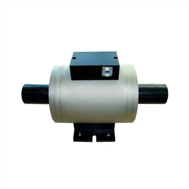
Rotary Torque Sensors
Rotary torque sensors are utilized in applications where the measurement must be taken at a spinning shaft or a stationary motor. In this case, the torque sensor must rotate in-line attached to the shaft. A rotary torque sensor is fitted with a slip ring or wireless electronics to transmit the torque signal while rotating.
Rotary Torque Sensors are frequently used as testing/auditing tools for motors, power tools, turbines, and generators. It can be also utilized for feedback control, monitoring torque, and analyzing the efficiency of test stands.
The Rotary Torque Sensor is coupled between the motor and the load. As the motor rotates, the Torque Sensor measures the torque produced by the motor in response to the load applied to the rotating shaft. Some Rotary Torque Sensors are equipped with built-in encoders. These encoders measure the angle/speed produced during the test. Torsion measurements can successfully be monitored on a local digital display, such as a Panel Mount Display, a Hand Held Display, connected to a PLC or streamed to a PC using a digital USB instrument.
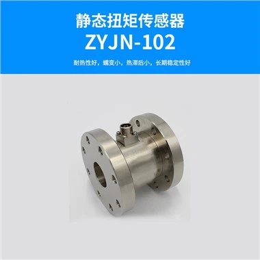
Reaction Torque Sensors
In some applications, the torque measured with an in-line rotary torque sensor may be measured at the point where the torque is transferred to the ground using a reaction torque sensor.
A reaction torque sensor has two mounting flanges. One face is fixed to the ground or a rigid structural member and the other to the rotating shaft or rotary element. Rotation generates shear forces between the flanges, which is captured by the foil strain gauges bonded to the sensor beams and transduced into electrical current by the Wheatstone bridge.
For a given application, a reaction torque sensor is often less complex and, therefore less expensive than a rotary torque sensor.
Micro Reaction Torque Sensor
Micro Reaction Torque Sensor provides a precision torque measurement solution for miniature, DC motors, servo motors. Traditional reaction torque sensors are bulkier. For reference, a micro reaction torque sensor dimensions are 22 mm in diameter and 10 mm in height, which is 5x times smaller than a typical reaction torque sensor. The significant reduction in size allows the micro reaction torque sensors to fit where most reaction torque sensors cannot.
Step 1: Installation
The first step is to install the torque sensor correctly. This process will vary depending on the type of sensor and its application. For instance, rotary torque sensors are typically installed in line with the rotating shaft or component you want to measure. Reaction torque sensors, on the other hand, are installed in line with a static object that's generating or being acted on by Torque.
Step 2: Alignment
Proper alignment is crucial for accurate torque measurements. All shafts should be aligned as accurately as possible to lessen the work of the couplings. Misalignment can lead to measurement errors and potential damage to the sensor.
Step 3: Calibration
Once installed, it must be calibrated to ensure accurate measurements. Calibration usually involves applying known torques to the sensor and adjusting its output until it matches the applied torques.
Step 4: Data Collection
With the sensor properly installed and calibrated, you can start collecting data. The sensor will convert the mechanical Torque into an electrical signal, which can be read and recorded by a data acquisition system.
Step 5: Data Analysis
The collected data can then be analyzed to assess the performance of the system or component. This might involve looking at peak torques, average torques, or how the torque changes over time.
Step 6: Maintenance
Regular maintenance, including periodic recalibration, can help ensure the torque sensor continues to provide accurate measurements over its lifespan.
5 Tips For Sensor Maintenance
If one part is not lined up as it should be, it is important to recalibrate and adjust accordingly. You will need proper measuring tools to do this correctly. Calibrating an instrument simply involves comparing one correct instrument to the one your are fixing. You can use that as a benchmark for all of the others.
Cleanliness is also key to keeping all moving parts performing their jobs correctly. At the end of the day, be sure to remove all debris and oil off the sensor. Also take the time to train all workers and employees in proper cleaning methods.
When your tool is not in use, take care to properly store it away. This could mean disassembling it until you need it again, leaving it on a sturdy surface, or covering it with a tarp, depending on the size and location of the tool.
Excessive rusting can cause a machine part to wear down even faster. If you are unable to remove corrosion on your own, consider hiring a professional or replacing the part entirely. Also be sure to keep moisture away from the tool as much as possible, preventing this in the first place.
Remember that sensor maintenance and cleaning only go so far. If you find yourself having to realign or repair a tool more often that it is worth, it is time to replace it. Check the tool’s warranty before you order a new model.
Our Factory
In 2018, the company was rated as an AAA credit rating enterprise; in 2019, it passed the ISO9001:2015 international quality management system certification. On August 17, 2020, it was rated as a national high-paying technology enterprise. In April 2022, it was rated as a specialized and special new technology enterprise in Jinan.


Certifications


