


In post‑tensioned prestressed bridge engineering, polymer corrugated ducts are critical components for protecting prestressing tendons and ensuring grout integrity. Incoming‑material acceptance and initial type testing shall strictly comply with widely‑accepted international technical specifications for polymer‑duct systems for internal bonded post‑tensioning (e.g., fib Bulletin 75).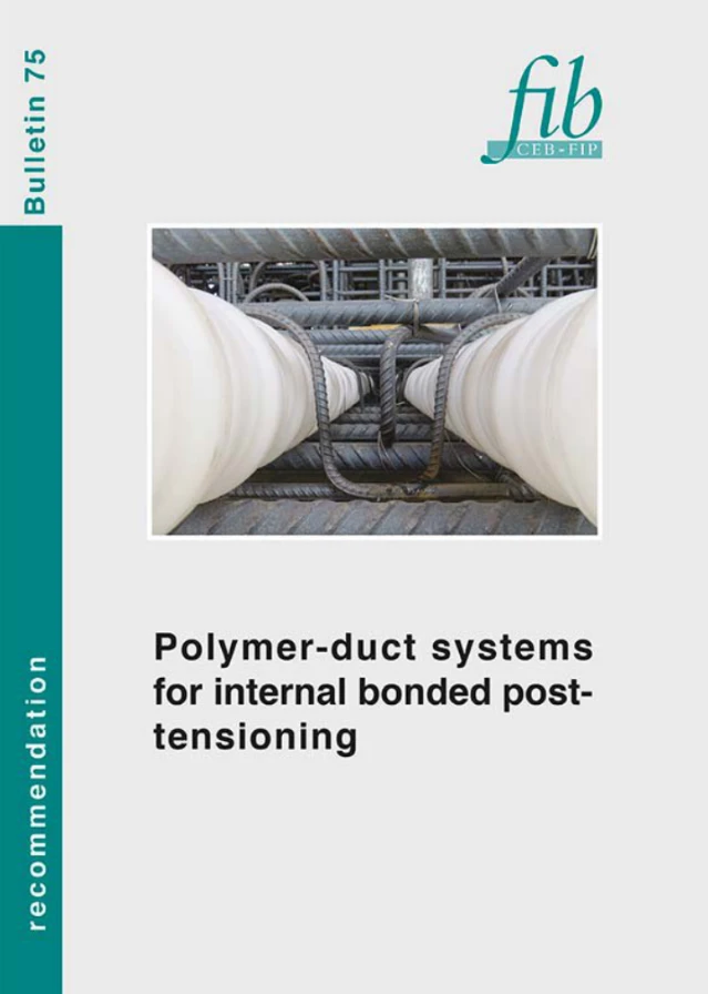
Within these specifications, base‑polymer tensile properties and longitudinal load resistance of duct assemblies are defined as two separate mandatory mechanical test items. Nevertheless, many testing and site‑construction personnel confuse their respective scopes, resulting in incorrect test execution and mis‑evaluation of acceptance criteria. This article explains the fundamental differences between the two tests with reference to specification clauses: the tensile test assesses the inherent strength of the duct material, whereas the longitudinal load‑resistance test verifies the reliability of joint‑coupler interfaces. Both tests are indispensable.
1. Tensile Test: Assessment of the Duct Base Material
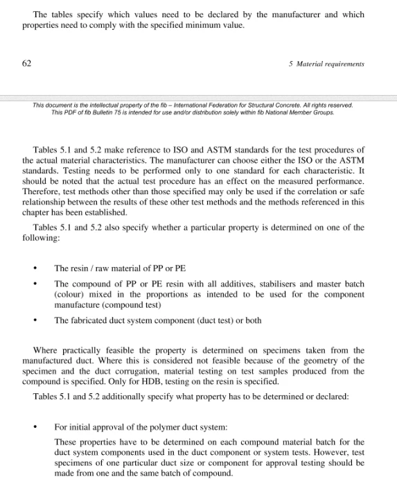
This test determines fundamental mechanical characteristics of the polymer base material of corrugated ducts, including yield strength, elongation at break and tensile modulus. It verifies whether the duct base material has sufficient strength and toughness to mitigate risks of duct cracking and brittle fracture.
In short: It evaluates the intrinsic strength and deformation capacity of the polymer duct material.
01 Test Specimen Standard specimens cut from plain corrugated‑duct segments, without couplers, anchor plates or additional assembled components. Only the HDPE duct base material is evaluated.
02 Loading and Failure Mode Standard duct specimens are clamped in a universal materials testing machine and stretched at a constant prescribed rate until fracture occurs in the duct base material. The force‑displacement curve is recorded throughout the test. Particular attention is paid to plastic deformation and fracture location; failure shall occur in the base polymer, not at any joint interface.

Nake universal materials testing machine
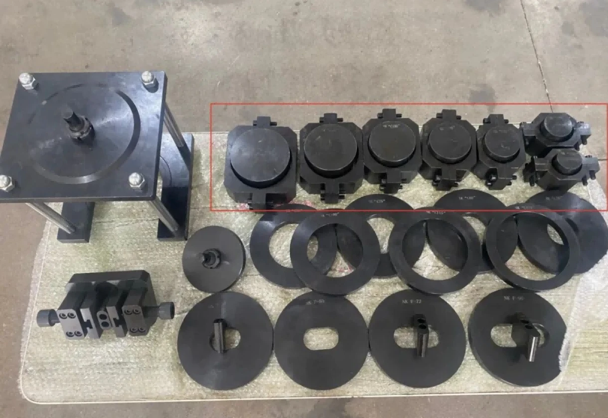
One pair of dedicated grips for each duct size, fitted at both ends
03 Engineering Significance This test controls the quality of raw polymer material for ducts. Insufficient tensile strength or elongation may lead to duct damage and grout leakage during tendon tensioning or concrete casting, which can cause failure of the complete prestressing system.
2. Longitudinal Load‑Resistance Test: Assessment of Joint Assembly Robustness
This test evaluates the bond and anchorage performance of the assembled interface consisting of anchor backing plate, duct coupler and corrugated duct. It simulates joint loading conditions under bridge tensioning operations and verifies resistance against joint separation and slippage.
In short: It examines the locking performance of duct‑to‑coupler and anchorage interfaces.
01 Test Specimen Complete assembled assembly: corrugated‑duct segment plus dedicated coupler plus anchor backing‑plate. A standalone duct segment is not sufficient for this test.
02 Loading and Failure Mode Axial tensile load is applied to the joint interface in incremental steps until interface separation between coupler and duct, anchor‑assembly pull‑out or joint disengagement takes place. Failure occurs at the duct‑coupler interface; fracture of the base duct material is not the expected failure mode.
 Test fixture for duct longitudinal load‑resistance test
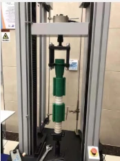 Test fixture for duct longitudinal load‑resistance test
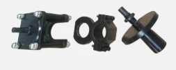 Field photograph of duct longitudinal load‑resistance test setup
03 Engineering Significance Large tensile forces are transferred via anchor heads during prestressing tensioning of bridges. Insufficient longitudinal load resistance may cause joint slippage during tensioning. This would compromise protection of prestressing tendons and rupture the grout channel, introducing critical structural‑safety hazards. This verification represents a strengthened requirement within international polymer‑duct system specifications.
Comparative Table of Key Differences Between the Two Tests
| Comparison Item | Tensile Test | Longitudinal Load‑Resistance Test |
|---|---|---|
| Reference Specification Clauses | Material‑property requirements referenced in fib Bulletin 75 Clause 5.2 (test method ISO 527) | Duct‑system longitudinal‑load resistance referenced in fib Bulletin 75 Clause 6.3, test procedure Annex A.3 |
| Core Evaluation | Mechanical performance of the duct base polymer material | Bonding and anchorage reliability of joints and assembly interfaces |
| Test Specimen | Plain corrugated‑duct segment specimen | Assembled set: corrugated duct + coupler + anchor backing plate |
| Expected Failure Location | Fracture of the polymer base duct material | Interface separation between duct and coupler joint |
| Acceptance Criteria | Yield strength, elongation at break | Ultimate longitudinal resistance load, no interface slippage |
| Risk Addressed | Brittle cracking and inferior raw‑material quality of ducts | Joint slippage and loss of sealing performance during tensioning |


